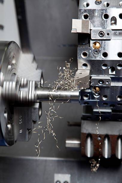
Machine tool collisions have always been an unavoidable challenge in prototype and part machining. Operator error, such as failure to set the tool, can cause collisions. In addition, in the absence of an automatic tool setter, incorrect Z value data entered during manual tool setting can also cause machine tool collisions. This article shares our experience to help you avoid this problem.

Before understanding how to avoid workpiece damage caused by machine tool collisions, it is necessary to understand the main causes.
The MasterCam NC programming software uses a method of machining using surface and line elements. If you don’t completely close the auxiliary surface and leave missing areas, you risk a machine tool collision. However, you can identify these risks through computer simulation machining verification, which checks for overcuts on the workpiece and helps avoid potential collisions.
There are commonly three setting problems that will cause the crashing.
Although the likelihood of this happening is low with regular maintenance and care of equipment and tools, it is still possible for tools to fall and collide during machining.
After identifying the main causes of machine tool collisions, you should implement effective preventive measures. This section guides you on using trial cutting methods to avoid machine tool collisions when you miss tool settings or enter Z value data incorrectly.
If the workpiece has a frame, you usually make a trial cut using the boundary line. As shown in the figure, the yellow line represents the boundary line, and you only need to test a short distance.
During the trial cut, the Z value height should be the same as the boundary height. With a straight distance of 200 mm and a feed rate of 3000 rpm, the test cut time is 4 seconds, plus the time for lowering and raising the blade is about 2 seconds, making a total of about 6 seconds. The above method is simple, and you test each tool in the same position. It is simply to check whether the tool setting is too deep to avoid overcutting or collision.
In most cases, with the exception of the scanning tool, you should test each machining tool in different areas. Adjust the machining depth to the frame plane by -0.02mm during the test cut. If you set the tool correctly, you will see light machining marks after the test cut. If the tool is too deep, deeper marks will appear. AIf the tool is too high, you will see no marks. Since this method relies on visual judgment, expect a margin of error of about 0.05-0.1mm. Unlike performing a test cut at the same position with each tool, this method allows you to check if the tool setting is too high. Adjust the number of test cuts according to the number of machining tools, as shown by the numbers in the figure above. However, each test cut requires manual judgement and each test cut takes about 2 minutes, so it is not suitable for mass production.
Are you looking for a reputable partner for your parts fabrication and machining projects? Look no further. At PROTO MFG, we specialize in CNC machining and related technologies, including sheet metal fabrication, rapid prototyping, etc. Whether it is a project with a simple design or parts with complex geometries, do not hesitate to contact us today!