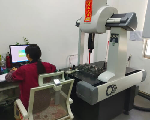
Geometric Dimensioning and Tolerancing (GD&T or GD and T) is a symbolic language and set of standards that engineers and manufacturers use to define a product’s geometry and dimensions. This system enhances communication among various entities involved in the manufacturing process.
GD&T is a method of describing dimensions and tolerances that differs from traditional coordinate measurement plus/minus tolerances. Essentially, engineers design parts in CAD with perfect geometry, but manufactured parts will never be perfect. GD&T, when used correctly, can improve quality and reduce lead times and costs. It does this by providing a common language to accurately express design intent and by focusing on the functional interface of part tolerances.
These are the main benefits of using Geometric Dimensioning and Tolerancing (GD&T):
There is a lot to learn to master GD&T, so this article will serve as a starting point to help you understand the most important GD&T basics and concepts, including:
The alternative to GD&T is coordinate measuring square tolerancing or “traditional tolerancing”. Square tolerancing uses square tolerance zones that form a rectangular box around the coordinates, while GD&T uses circular/cylindrical tolerance zones that form a rectangular box around the points, resulting in GD&T tolerance zones that are 57% larger. In addition, Coordinate Measurement Systems do not clearly define inspection requirements or design intent, whereas GD&T can succinctly define both.
Tolerance http://www.mfgproto.com, the “T” in GD&T, is the amount of variation allowed in a physical dimension. Tolerances on an engineering drawing must be kept in perspective – the tolerances on a particular part may not be visible to the naked eye, but they can have a major impact on the performance of the part or assembly. When you look at CNC machined parts, they appear flat and straight, but if you were to accurately measure every cross section of the part, you would see many imperfections. These variations or imperfections are allowed within the tolerance range of the part – when choosing tolerance ranges we understand that all parts will have varying degrees of imperfections.
In general, an engineer or designer should try to maintain as wide a tolerance as possible while still ensuring the functionality of the part. Tolerances that are too small or too tight can increase the cost of manufacturing, testing and tooling the part. Sometimes tight tolerances are necessary, but it’s better to keep them as wide as possible to save costs. To give some context to tolerances, let’s look at the average human hair, which has a diameter of about .005 inches. In general, today’s CNC milling machines can achieve tolerances of +/- .005 inch. However, just because you can achieve tolerances smaller than a human hair doesn’t mean you have to (or should). Follow our guidelines for specifying CNC machining tolerances.
In general, an engineer or designer should try to maintain as wide a tolerance as possible while still ensuring the functionality of the part. Tolerances that are too small or too tight can increase the cost of manufacturing, testing and tooling the part. Sometimes tight tolerances are necessary, but it’s better to keep them as wide as possible to save costs. To give some context to tolerances, let’s look at the average human hair, which has a diameter of about .005 inches. In general, today’s CNC milling machines can achieve tolerances of +/- .005 inch. However, just because you can achieve tolerances smaller than a human hair doesn’t mean you have to (or should). Follow our guidelines for specifying CNC machining tolerances.
GD&T is a feature-based system and all engineering parts are made up of features. Geometric tolerances are applied to features through the feature control framework, using a set of symbols to describe the tolerances allowed. When people think of GD&T, it is these symbols, or geometric features, that most often come to mind. There are many features for GD&T and some of the most commonly used symbols that represent these features are listed in the symbol “cheat sheet” below.
These features and their symbols fall into four main categories (or feature types): shape, orientation, location and concentricity.