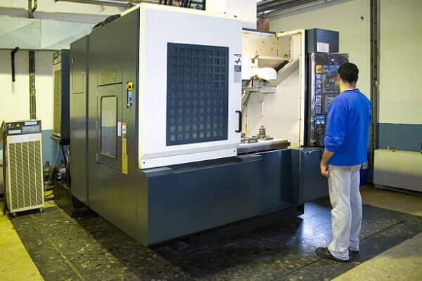
CNC – Computer Numerical Control – uses digital data to guide, automate and monitor the motion of a machine. The machine can be a mill, lathe, router, welder, grinder, laser or water jet cutter, sheet metal stamping machine, robot or many other types of machine. For larger industrial machines, the computer is usually a dedicated on-board controller. But for more hobbyist types of machine, or with some retrofits, the computer can be an external PC. The CNC works with a series of motors and actuators to move and control machine axes, performing programmed movements. On industrial machines, sophisticated feedback controls are used to monitor and adjust the speed and position of the blade.
Desktop CNC – There are many smaller, hobbyist style desktop CNC machines. Some desktop machines can operate much like a printer. Others have their own closed command system and may even have their own CAM software. A few will also accept standard G-code as input. There are also some industrial standard desktop machines with dedicated controllers for small precision work.
CAM is the use of various software packages to create tool paths and NC code to run a CNC-controlled machine, based on 3D computer model (CAD) data. When the two are used together, it is generally referred to as CAD/CAM. CAM only creates code for the CNC machine to follow, it does not actually run the CNC machine.
Nor is it an automated process that imports your CAD model and spits out the correct NC code. CAM programming, like 3D modeling, requires knowledge and experience of how the program works, how machining strategy is developed and which tools and operations are used for the best result. There are simple programs that can be used by inexperienced users without too much difficulty. However, more sophisticated models require an investment of time and money to become proficient.
Postprocessor – Although G-code is considered the standard, each manufacturer can modify certain parts, such as auxiliary functions, so G-code written for one machine may not work on another. There are also many machine manufacturers, such as Heidenhain or Mazak, that have developed their own programming languages. To translate the CAM software’s internally calculated paths into specific NC code that the CNC machine can understand, there is a bridge piece of software called a post-processor. In theory, any CAM system can output code for any machine, as long as the post-processor is configured correctly. Postprocessors can come free with the CAM system or be an extra cost.
CNC machines can have multiple axes of motion, and these motions can be either linear or rotary. Many machines have both. Cutting machines, such as lasers or waterjets, usually have only two linear axes, X and Y. Milling machines usually have at least three, X, Y and Z, and may have more rotary axes. A five-axis milling machine is one that has three linear axes and two rotary axes, allowing the cutter to work in a full 180º hemisphere and sometimes more. There are also five-axis lasers. A robotic arm can have more than five axes.
Depending on their age and sophistication, CNC machines can be limited to the capabilities of their control and drive systems. Most CNC controls only understand straight line movements and circular arcs. On many machines, arcs are also limited to the main XYZ planes. The movements of the rotary axes can be thought of as linear movements, only in degrees instead of distances. Two or more axes must interpolate (move precisely in synchronisation) to create arcs or linear motion at an angle to the principal axes. Linear and rotary axes can also interpolate simultaneously. In the case of five-axis machines, all five axes must be perfectly synchronised – no easy task.
Machine controls must be able to receive and process incoming data quickly, send commands to drives, and control machine speeds and locations. This is similar to how an older computer may not perform as well or as fast (if at all) as a new computer.
2 axes if all the cuts are made in the same plane. In this case, the cutter cannot move in the Z (vertical) plane. Generally, X and Y axes can interpolate simultaneously to create angled lines and arcs.
3-axis if you need to control X, Y and Z movement while cutting (necessary for most freeform surfaces), use 3-axis.
4-axis When the above motions are added to 1 rotary axis motion, there are 4 axes. There are two possibilities: 4-axis simultaneous interpolation (also called true 4th axis). Or just 4th axis positioning, meaning the 4th axis can reposition the part between 3-axis operations, but does not move during machining.
5-axis if it includes the above plus 2 rotary axis movements. As well as true 5-axis machining (5 axes moving simultaneously during machining), you often have 3 plus 2 or 3 plus 2 separate axis positioning only, and in rarer cases 4 plus 1 or continuous 4 axis machining + a single 5th axis positioning only.